
A Closer Look
As part of the original 2013 NeoLucida crowdfunding campaign, I answered some frequently asked questions about the history and design of the camera lucida in the form of short art history essays we called "Interludes." People were enthusiastic about a tool that helps them draw, but didn't know a lot about this forgotten tool. They had a lot of questions. So I put on my art professor hat and got writing.
What exactly is the magic inside that tiny prism?
For more camera lucida essays, here are "The NeoLucida Interludes":
It's a little bit more than just a "prism on a stick."
The camera lucida, patented by William Hyde Wollaston in 1807, is essentially a “prism on a stick.” The stick part is easy to understand, but exactly how does the prism work? What sorcery lives in that little block of glass? In this “Interlude” update, our fourth, we present a detailed “how it works” about camera lucida optics. Along the way, you’ll see how we came to make some of our decisions about the optical design of the NeoLucida.
1. How does a camera lucida overlay two images?
Camera lucidas allow you to “trace what you see” by superimposing two views: that of your subject (such as a landscape, portrait, still life, etc.), and that of your paper.
Historically, there have been two basic design paradigms for the camera lucida. As a shorthand, we’ll call these the “See-Through” design, which uses planes of glass and mirrors, and the “Split-Pupil” design, which uses a solid glass prism. (Of course, there are many other technologies for “tracing what you see”, such as opaque projectors, the camera obscura, and even tracing paper—but these use entirely different optical principles.) The “See-Through” design was developed more recently, and is used in commercial devices like the Lucid-Art; we’ll discuss it first.
The “See-Through” camera lucida makes use of an angled piece of transparent or semi-transparent glass. When you look through the glass, you see the reflection of your subject plus your paper at the same time, superimposed. If you’ve ever seen a double-image in a glass storefront, that’s the principle. When the lighting is well-balanced between inside and out, you’ll see two images superimposed like this:
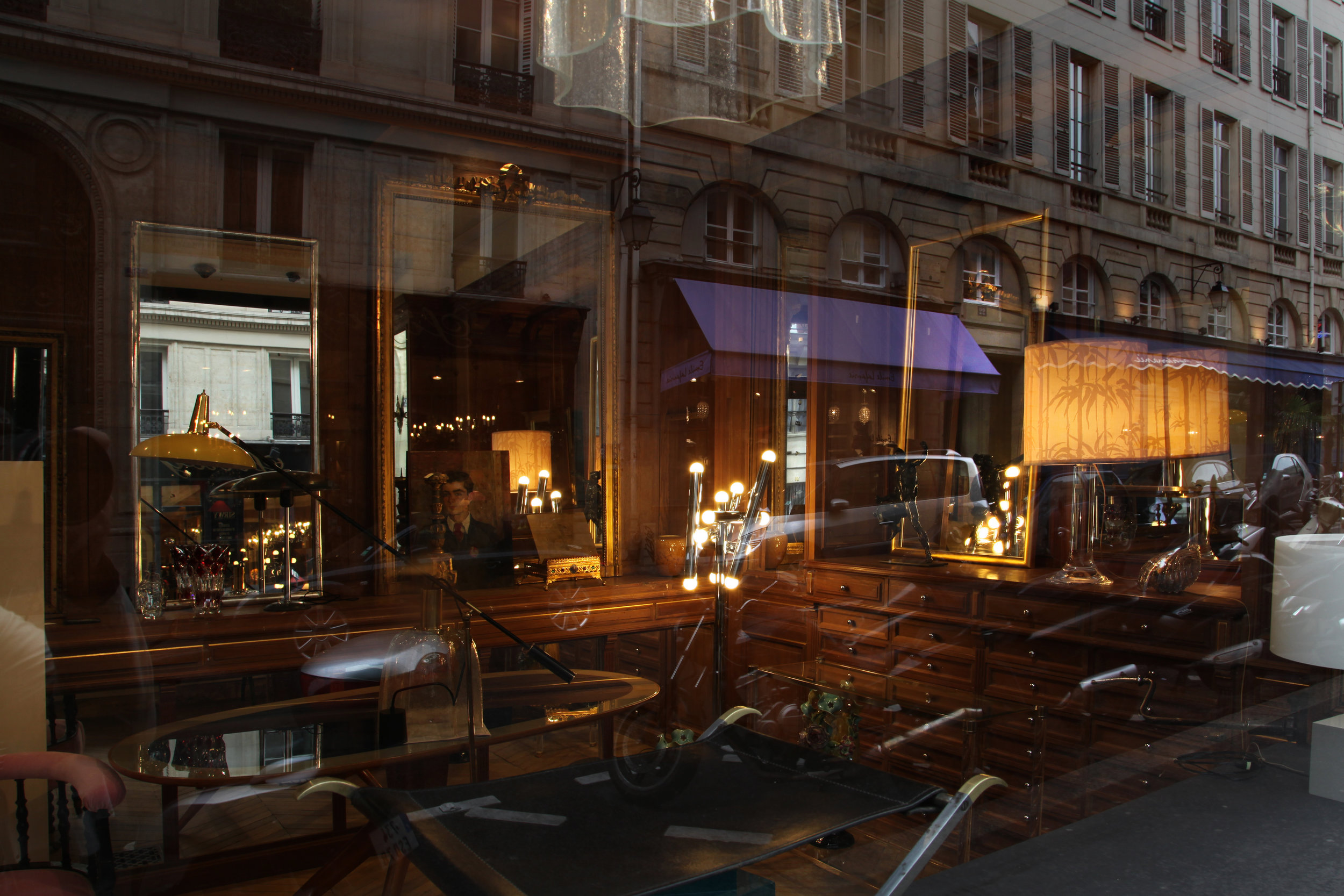
Paris, 2012. Photo by Pablo Garcia
Both the 1950s “Magic Art Reproducer” and the 1930s “Graphoscope” (mentioned in Interlude #3) employed this design scheme to make an inexpensive camera lucida for mass production. But the use of this design goes back even further, to variations on the camera lucida in the 19th century. For example, the English optician Alexander Alexander (that’s his name!) used this technique in his “Graphic Mirror” drawing tool, circa 1840.
Alexander’s Graphic Mirror, The Magazine of Science, Jan. 25, 1840.
Because the “See-Through” design uses readily available optical materials like plate glass and mirrors, it can be an effective yet inexpensive method for producing the lucida’s necessary image overlap. But it’s not without problems. First, for example, this setup is particularly susceptible to failure when there are lighting disparities between the scene and paper. If the scene and paper are not equally bright, it can be difficult to get a satisfactory superimposition of the views: the brighter image will always win.
A second problem of the “See-Through” design is a lack of sharpness due to extra reflections. This is an inevitable consequence of using plate glass mirrors, which produce a double-reflection—one from the mirrored (silvered) side of the glass, and one from the other (front) surface of the glass:

Typical mirror (left) is a rear-surface mirror applied to glass. Multiple reflections from this setup cause image confusion.
The user’s view may therefore be a composite of up to four reflections, each showing the scene from a slightly different angle and position. The eye interprets these as “out of focus”—and therefore difficult to trace. This can be mitigated by the use of pellicle beam splitters (a kind of reflective film) and first-surface mirrors (such as polished metal), but these are considerably more expensive and highly susceptible to damage (such as from dust, fingerprints, oxidation, and scratches).
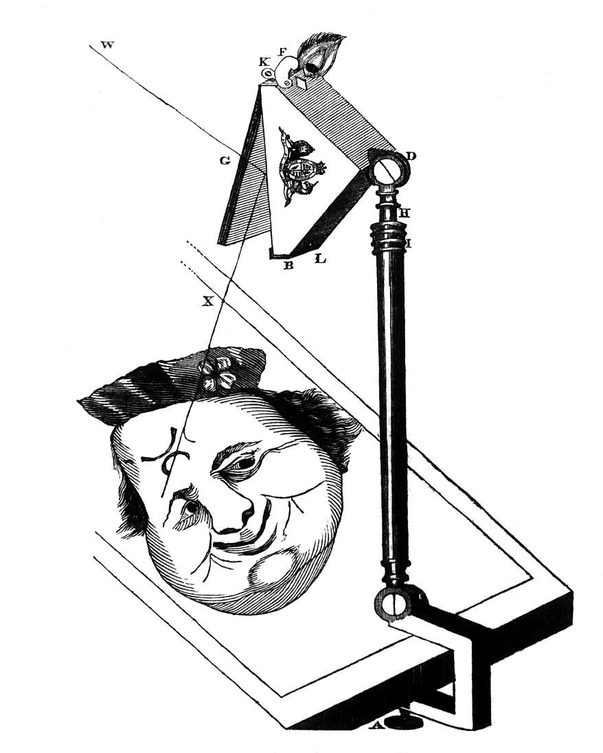
Giovanni Battista Amici, an Italian 19th century astronomer and mathematics professor, was among the first to propose “See-Through” alternatives to Wollaston’s foundational prism design. He thought the proximity of the eye to the prism’s edge was too close for comfort, and so he developed a variety of models with combination glass and mirror elements. In Sopra le camera lucide (1818), he concedes the basic flaw in his design—and in all “See-Through” camera lucidas to follow. This diagram is adapted from Amici’s paper (note: we have colored Amici’s image and added the eyes above it):

Here is one of Amici’s proposals for a “See-Through” camera lucida, in 1818. Amici’s design uses a clear glass plane, shown here in pink cross-section, and (to its left) an adjacent front-surface mirror. In Fig. 2, Amici illustrates the vertical optical path OQwhich allows the viewer to see their paper. In Fig. 3, Amici points out the difficulty caused by multiple reflections: Optical path HCBA (in Fig. 3) is the preferred line of sight, and produces a nice image. But part of your eye will necessarily see pathGFDCBA as well.
The “Split-Pupil” design is the other major type of camera lucida, and was indeed the first design, devised and patented by William Hyde Wollaston in 1807. It’s also the core design scheme that we use in the NeoLucida, though we employ a prism shape that became common a few decades later.
The “Split-Pupil” design involves a small prism positioned so that your eye looks down at its leading edge. This arrangement splits your vision between the prism image and your paper—and your brain interprets the split view as a pair of overlapping images.

Your eye (E) stares at the edge of the prism at (B). The prism edge splits your vision between looking at your pencil at (P) and the reflected image of your subject (S). The result is seeing (S) at (S’’’) overlapping your page. Trace away!
Because the reflections in the prism are completely internal to the glass block, there are no unwanted additional reflections. This produces the effect of a sharper image.
2. How does it show the subject right-side up?
A simple camera lucida—in fact, the simplest possible camera lucida—can be made with a single piece of glass.
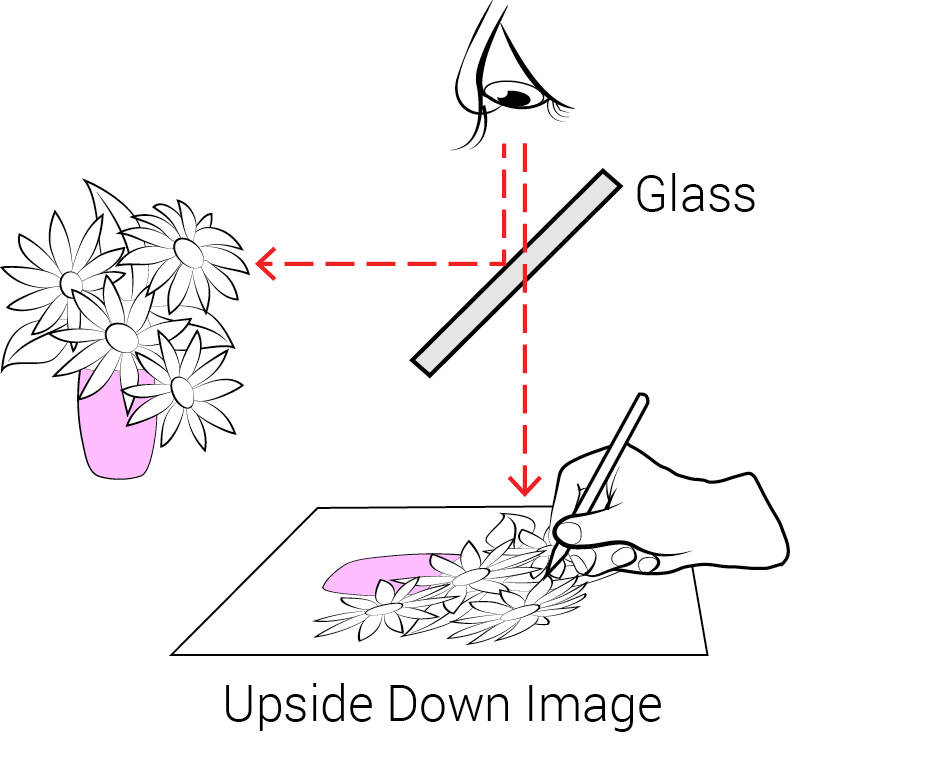
Unfortunately, this design displays the viewer’s subject upside-down. We think it can be difficult and distracting to trace an upside-down image, and so we selected a design for the NeoLucida which, as with most other camera lucidas, allows you to see your subject right-side-up.
All of the prism-based “Split-Pupil” designs allow for right-side-up viewing and tracing. In these designs, the prism causes the light to make two reflections before getting to your eye. This “double-inverts” the image, in which the first inverted reflection is inverted again, into a non-reversed, right-side-up image. The early success (and patent) of Wollaston’s original camera lucida prism prompted competitors to explore a wide variety of alternative prisms. Their geometries varied, but all worked on the same simple premise: reflect the image twice.

Charles Chevalier, from “L’Art du Dessin” 1838
Few of these alternative solutions were ever put into practical production. Wollaston’s design remained the standard until the late 19th century, when the Parisian optician Pierre Berville designed and popularized the silvered prism we now use in the NeoLucida. Whereas Wollaston’s unique prism is 4-sided, Berville’s is a 45-90-45 (right) triangular prism with a mirror-faced hypotenuse. We elected to fabricate the NeoLucida’s Berville prism from strong, environmentally friendly H-K9 glass, using a tarnish-resistant aluminum mirroring and a protective black paint overcoat.
3. Why is the NeoLucida’s prism so small?
The NeoLucida prism copies the exact dimensions and design of antique Berville prisms. These prisms are small, just a few millimeters on a side. So it’s reasonable to ask: wouldn’t a larger prism have been better? Well, a larger viewing element does give a wider field of view—but it does so at the expense of precision. As surprising as it may seem, the small size of the Berville prism offers users a superior experience because it eliminates parallax and therefore allows for precise alignment for copying.
The most important issue in successfully tracing anything is registration. That is, you want your original and your tracing to stay in perfect alignment as you draw. This is trivial if you lay tracing paper over a printed image. But with a camera lucida, the paper, your eye, and the apparent image of your subject in the prism are all in different planes. Any slight movement of your head causes the subject’s virtual image to shift! And that’s the main problem with larger viewing elements, whether in “See-Through” or “Split-Pupil” lucidas. If you move your head while using a large viewing element, you “lose your place”— and finding it again can cause a frustrating loss of registration.
Historically, some camera lucidas have solved this problem by including tiny pinhole apertures in the prism housing. There’s only one possible place to put your eye, so parallax issues are completely eliminated. In comparison to these antiques, the NeoLucida’s 10mm-wide viewing area is relatively generous!
